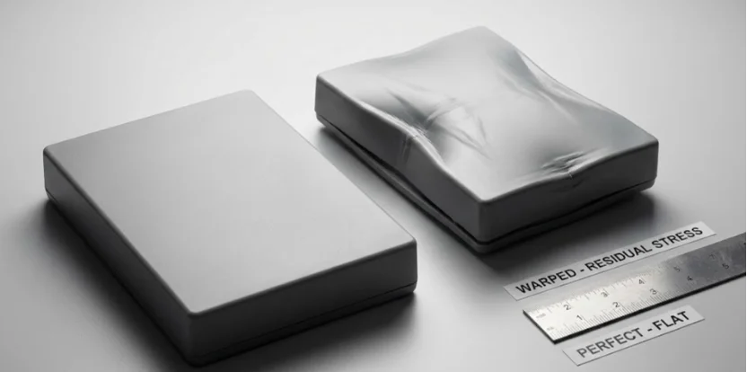
Stress marks are rarely solved by changing one injection-molding parameter at random. A part may leave the mold looking acceptable and develop whitening, crazing, or visible stress around a gate, corner, rib, or ejection point afterward. That behavior usually indicates that mechanical or thermal stress has been introduced somewhere during filling, packing, cooling, or demolding.
For engineers trying to how to get rid of stress marks, the more useful approach is to locate where residual stress enters the component and then correct that stage. HordRT’s injection-molding guidance identifies material selection, mold design, processing conditions, and ejection as interconnected factors in stress prevention.
Find Out Where the Stress Is Being Created
A stress mark should first be treated as a symptom rather than a diagnosis. Its location can provide an initial clue. Marks concentrated around the gate may indicate excessive shear or restricted flow. Similar defects near ribs, bosses, sharp corners, or ejector locations can point toward local geometry or demolding forces.
The material also matters. Some polymers are more sensitive to residual stress than others, particularly when molecular orientation becomes trapped during processing. Material drying, melt condition, and the selected resin grade therefore need to be considered before changing the machine settings.
Stress-related issues in molded parts can be influenced by factors such as part geometry, material properties, mold construction, and molding parameters, so these factors may need to be considered together during design and process evaluation.
A useful troubleshooting process begins with the defect pattern. Where does the mark appear? Does it occur consistently in the same location? Does it become more obvious after assembly, chemical exposure, or mechanical loading? Those observations narrow the potential causes before adjustments are made.
Start With Flow Restrictions Around the Gate
The gate is one of the first places to investigate because molten plastic experiences substantial shear as it enters the cavity.
A gate that is too small, poorly positioned, or unsuitable for the material can increase flow resistance. Rapid filling through a restrictive opening can create strong molecular orientation and localized stress, which may later become visible as whitening or cracking.
Gate position also determines how the melt travels through the cavity. If the flow path forces the material through narrow sections before reaching thicker regions, the resulting pressure and shear conditions may become uneven.
HordRT’s stress-prevention guidance emphasizes appropriate gate design and placement as part of reducing molding stress. Its general injection-molding design guidance also recommends considering gate size and location according to the material and component geometry.
Changing the gate is not always necessary. Sometimes a modest adjustment to injection speed or melt temperature can reduce excessive shear. If the same defect remains localized around the gate after reasonable process optimization, however, the tooling itself may require review.
Check Whether Packing Is Overloading the Part
Filling the cavity is only part of the cycle. After the cavity reaches the intended fill state, packing pressure continues to influence the part while the polymer cools and contracts.
Excessive packing can force additional material into constrained regions and increase internal stress. The effect may be especially noticeable around thick-to-thin transitions, ribs, bosses, and other areas where shrinkage is not uniform.
Injection speed should therefore not be viewed independently from holding pressure and holding time. Increasing one parameter to compensate for a problem created by another can simply move the defect rather than eliminate it.
A better approach is to establish whether the defect changes when packing pressure or hold time is reduced while maintaining adequate part filling. If dimensions remain acceptable but visible stress decreases, excessive packing may have been contributing to the problem.
The objective is not to use the lowest possible pressure. It is to provide enough packing to control shrinkage without creating unnecessary residual stress.
Look at Cooling Before Changing the Material
Cooling can lock stress into a molded component just as easily as filling can introduce it. A part with uneven wall thickness does not necessarily cool at the same rate throughout its geometry. Thick areas retain heat longer than thin sections, while poorly balanced mold cooling can create additional temperature differences across the cavity.
Those differences can produce uneven contraction and residual stress. HordRT’s injection-molding guidance emphasizes uniform wall thickness and balanced cooling as important factors in reducing molding defects and internal stress.
The mold temperature also deserves attention. Raising or lowering it without understanding the material’s processing requirements can create new problems. A controlled mold-temperature strategy can give the polymer more uniform conditions during solidification and reduce the amount of stress retained in the finished part.
Before switching resin grades, engineers should therefore examine wall-thickness transitions, cooling-channel placement, and actual mold-temperature uniformity.
Treat Ejection as a Potential Source of Visible Stress
Sometimes the molding process creates a sound part, but demolding damages it.
Insufficient draft, rough cavity surfaces, poorly positioned ejector pins, or excessive shrinkage around core features can make the part difficult to release. Ejector forces then concentrate on small areas rather than being distributed across the component.
The resulting marks may appear around ejector pins or other release features and can become more obvious when the part is subsequently flexed or assembled.
HordRT’s guidance identifies proper draft, suitable ejection design, polished mold surfaces, and balanced ejector placement as important considerations for reducing stress during removal.
This is why how to get rid of stress marks cannot be answered entirely through machine settings. If the defect is created during ejection, reducing injection pressure will not address the underlying mechanical force. Inspecting the mold surface and observing how the part releases can reveal whether the component is sticking before the ejector system pushes it free.
Prevent Stress Marks by Correcting the Whole Molding System
Once the likely source has been identified, process changes should be made systematically rather than simultaneously. A practical sequence is to examine the material first, then review gate and flow conditions, packing behavior, cooling uniformity, and finally ejection. Each adjustment should be followed by inspection so that the effect of the change can be separated from the previous condition.
Part design may ultimately require modification. Sharp corners can concentrate stress, while abrupt wall-thickness changes can produce uneven filling and cooling. Adding appropriate radii, improving thickness transitions, or relocating gates can sometimes provide a more durable solution than repeatedly tuning the molding machine.
HordRT‘s manufacturing guidance treats stress prevention as a combination of DFM, mold design, material preparation, process control, and inspection rather than a single parameter adjustment.
That approach is especially important when a defect appears intermittently. A process that produces acceptable parts only under a narrow set of conditions may still have an underlying design or tooling weakness.
How to get rid of stress marks comes down to identifying where the polymer is being forced, restrained, cooled, or released unevenly. Gate restrictions can increase shear, excessive packing can lock in molecular stress, uneven cooling can create differential shrinkage, and difficult ejection can mechanically damage the finished surface.
Treating those causes as separate diagnostic possibilities makes troubleshooting much more efficient. Instead of continually adjusting injection pressure or temperature, engineers can trace the defect back through the entire molding cycle and correct the stage responsible for creating it. That produces not only cleaner surfaces, but also a more stable process and parts with lower residual stress.