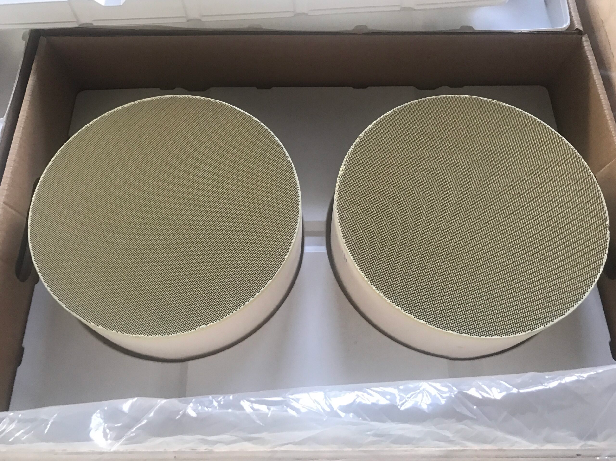
An SCR catalyst and a DPF can occupy the same diesel exhaust system without doing the same work. Selective catalytic reduction targets nitrogen oxides, or NOx, through reactions involving ammonia derived from urea. A DPF captures soot in porous walls. Their integration becomes difficult when flow resistance, temperature, or regeneration conditions suitable for one device are assumed to suit the other without measurement.
The design task is to define the inlet conditions each device needs and the outlet conditions it creates. Reductant delivery and SCR activity depend on temperature and gas composition; soot loading changes filter pressure and can call for added heat. On one exhaust path, a selective catalytic reduction catalyst addresses NOx while a dpf exhaust filter captures soot; those duties require different measurements.
Assign Each Pollutant to Its Treatment Mechanism
NOx is not removed by passing exhaust through a soot filter. In SCR, ammonia reacts with NOx over an active catalyst to form nitrogen and water. The useful reaction rate depends on temperature, NO/NO₂ balance, reductant availability, and contact with the catalyst surface. Too little reductant or a poorly matched temperature window can leave NOx untreated even if the honeycomb itself fits the pipe.
Soot accumulates on porous ceramic filter walls because alternating blocked channels redirect the exhaust stream across them. The filter does not replace the chemistry of selective catalytic reduction catalysts. As the deposit grows, pressure drop changes, so filtration capacity and regeneration behavior have to be considered over time. The two units address different pollutant classes and generate different kinds of operating data.
Reductant mixing creates an interface that a filter specification cannot solve. Uneven ammonia distribution can leave parts of the SCR face underused even when the average dose is correct. The DPF’s task remains soot capture; its performance cannot compensate for poor reductant distribution or an SCR catalyst operating outside its useful temperature range.
Manage Temperature and Pressure between Devices
Temperature governs when SCR chemistry is useful and when soot can be removed from a filter. Sufficient exhaust heat can burn deposited soot; otherwise, controlled heating is required to regenerate the filter. The temperature profile experienced by an SCR unit may change during such events. An integrated layout needs to account for normal operation and regeneration, not just a stable point used for nominal sizing.
Pressure is cumulative along the exhaust path. A low-loss SCR honeycomb does not erase restriction from the filter, and a clean DPF does not represent the pressure seen after soot accumulation.
Measurements at several flow and loading states show whether the combined system remains within the engine’s allowance. Channel density and dimensions can then be adjusted with awareness of their effect on both treatment and resistance.
The dpf exhaust filter also needs physical room for installation and service. A packaging change may alter pipe lengths, sensor positions, or the distribution of exhaust across a filter face.
Those changes can affect measured temperature and pressure at the SCR inlet. The installation drawing fixes these interfaces and the locations at which component requirements are evaluated, including whether a sensor represents the gas actually entering the SCR.
The order of the devices also matters to temperature and service planning. If an SCR unit receives exhaust after a filter, regeneration events can alter its inlet conditions; another layout changes the interfaces that need checking.
No universal sequence follows from the names of the components alone. Drawings and tests must state the actual order, sensor locations, and control strategy before an integrated performance claim is made.
Validate the Functions without Merging the Metrics
NOx conversion and particulate capture require different measurements. The first follows gas concentrations across the SCR system under defined dosing and temperature conditions; the second follows soot retention and filter behavior under a stated loading and regeneration cycle. One favorable result cannot stand in for the other. The engine’s overall pressure and thermal limits form a third set of criteria.
Separate component choices remain necessary even within one supplier’s range. Urea-SCR chemistry in Hualian Catalyst‘s diesel catalysts uses vanadium-based or molecular-sieve-based active options; the low-pressure-drop honeycomb can be tailored in size, cell density, and formulation. Cordierite or SiC wall-flow DPF products address the filtration duty. Their pairing must accommodate the temperature and pressure conditions of the target engine.
Hualian’s selectable SCR chemistry and DPF material options permit application-specific combinations, but selection requires data for the same engine duty. A vanadium-based formulation and a molecular-sieve-based formulation may respond differently to exhaust temperature.
Regeneration heat and installation loads can affect Cordierite filters differently from SiC filters. The comparison belongs in a documented operating envelope rather than a generic claim of compatibility.
The integration process ends with a map of responsibilities: the selective catalytic reduction catalyst handles the specified NOx duty, the dpf exhaust filter handles soot, and the installed assembly remains within flow and thermal limits.
Results from unmatched configurations cannot establish how the installed system performs. A system is convincing when its separate pollutant results and combined engine effects are all visible in the same evidence set.